project12:W4G1Sensor

Group 1: Alara - Francesca - Romeny - Michael - Taija
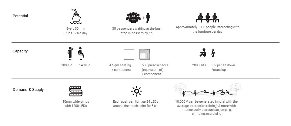
SYSTEM
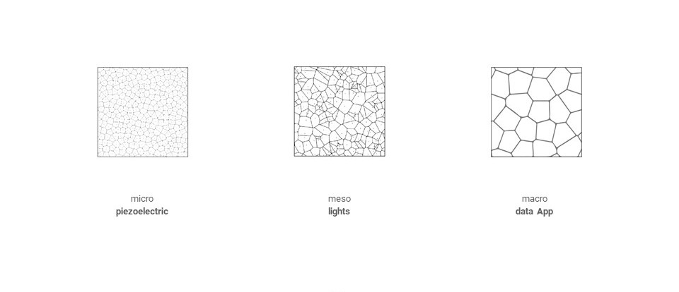
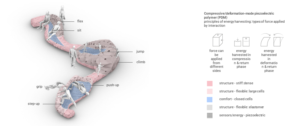
SCALES OF SENSOR-ACTUATOR SYSTEM
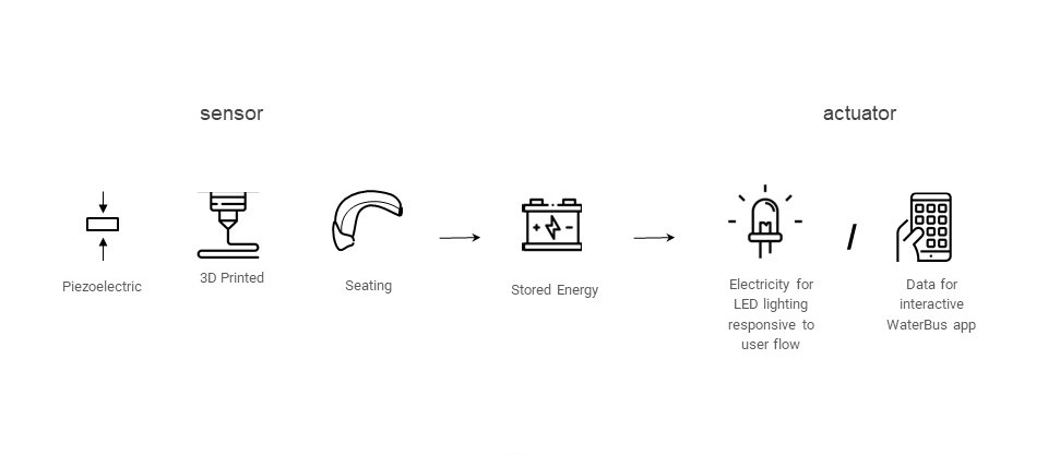
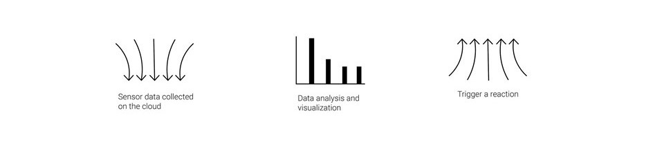
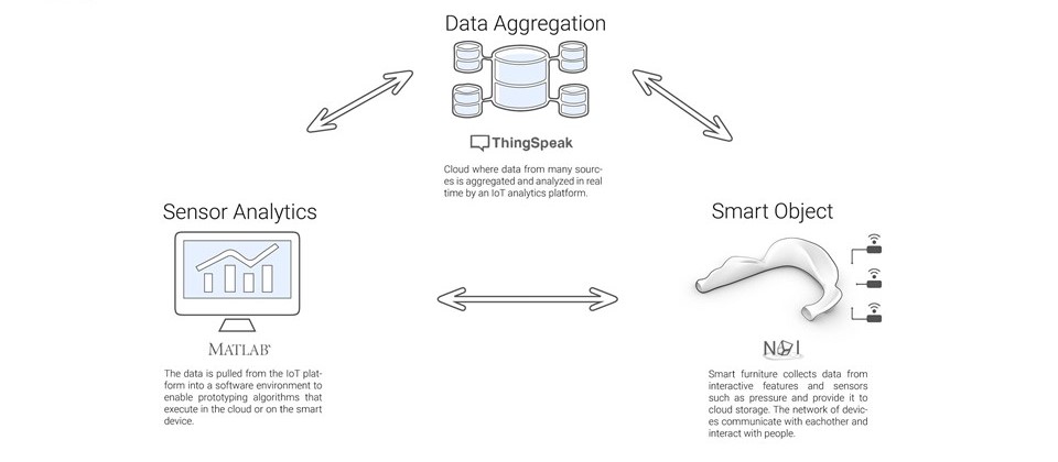
 SENSOR-ACTUATOR SYSTEM
SENSORS MATERIALITY
MATERIALS SOURCING: CIRCULAR, LOCAL, RECYCLED PLASTIC
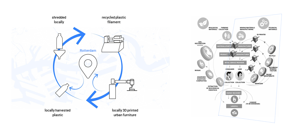
MATERIALS IMPLEMENTATION
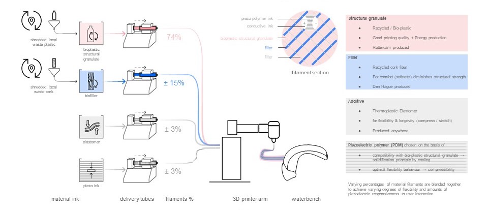
MATERIALS IMPLEMENTATION - MAPPING
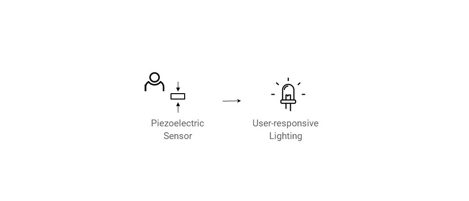
ACTUATORS
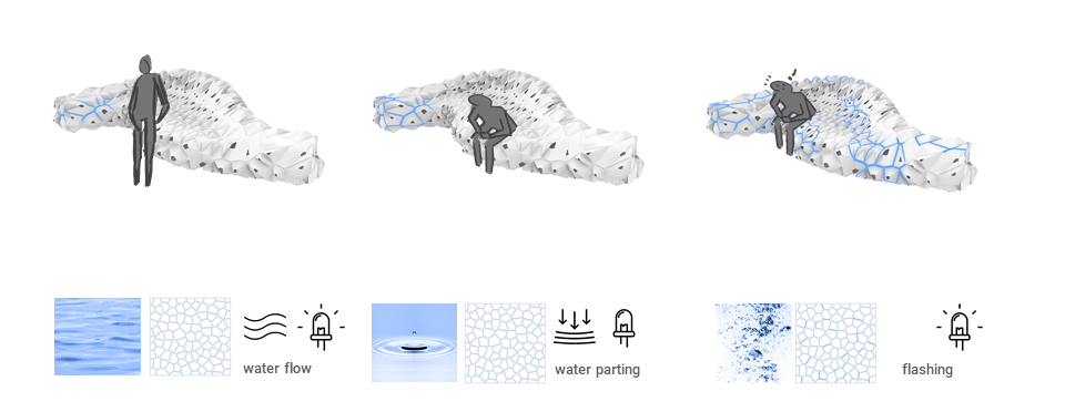
ACTUATOR 1: LIGHTING
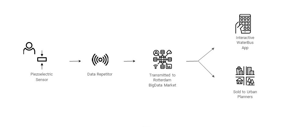
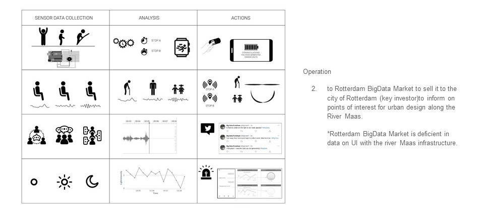
ACTUATOR 2: BIGDATA
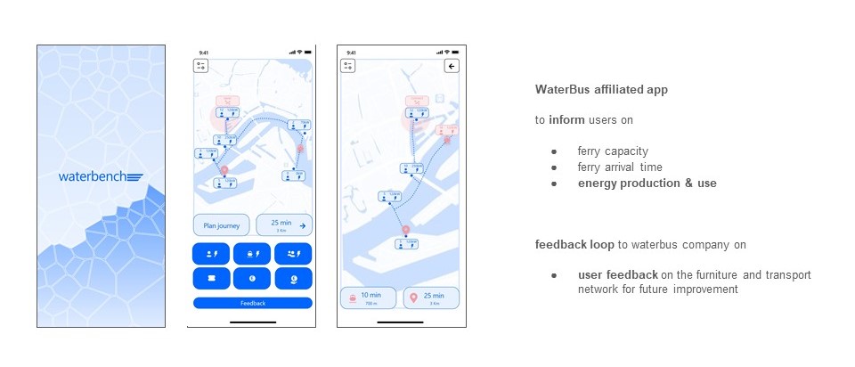
 USER INTERFACE
BIGDATA TO PLANNERS
HOW IT WORKS
INTEGRATION
AREA OF FOCUS
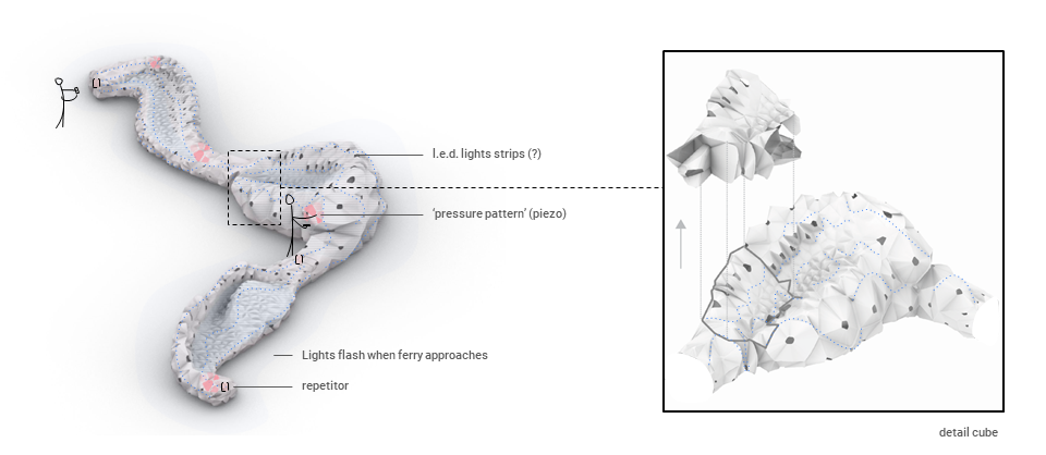
LIGHTS
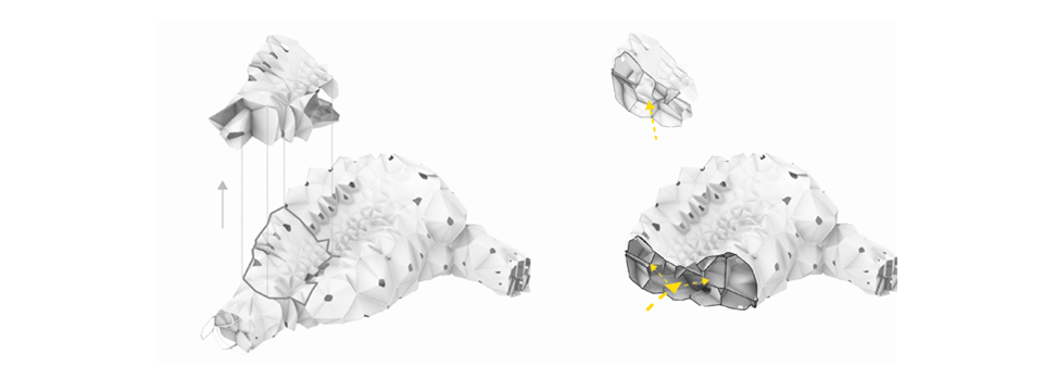
MACRO
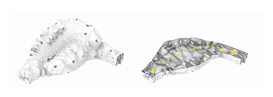 Canal at base of module: A canal for the lighting has been designed into the base of each module.
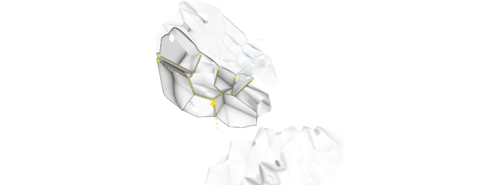
MESO
 Canal within each component: Each component is printed separately. A canal for lighting has been designed within each component in which the lighting is threaded through
MICRO
Canal at micro level: The lights are then threaded through canals at the micro level and closed with a pvc cap
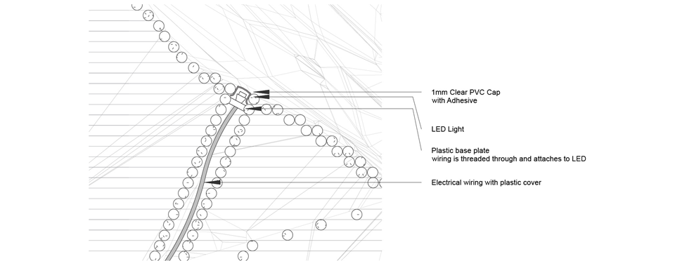
Canal at micro level: The lights are then threaded through canals at the micro level and closed with a pvc cap
MAGNETIC PADS
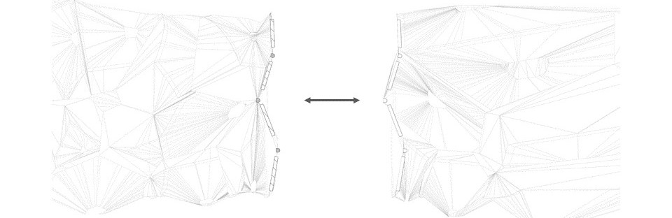
Final stage of the construction is the integration of magnets and sensors at the interlocking component. Strong magnets have been fitted into the voronoi cells in order to join the modules in a smooth way. Between the magnets, integrated as per the lighting at the vertex of the cell, are sensors that transmit the information regarding the lighting in order to achieve a fluid lighting experience across the modules.
BATTERY
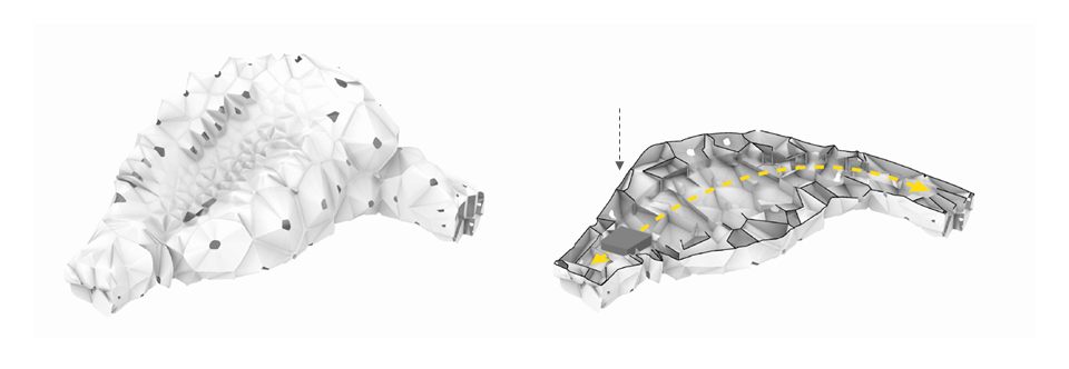 Canal at base of module: An enclosed compartment has been designed into the module in which the battery and raspberry pi is placed.
ENERGY CALCULATIONS